Some Interesting Energy Systems:
A Simple Lamina Flow Engine
I learnt of this engine, at an International Stirling Engine Conference, some years ago. In discussions with Jim Senft he referred to it a Lamina flow engine, in US patents it is usually called an acoustical heat engine. Jim's explanation seemed, at the time, clear however on my return to the UK it was evident I had not fully understood the theory since I failed to get an experimental engine to work! Subsequent research unearthed patents and other literature dating back to the 1950's, these clarified the working cycle of this type of engine.
The schematic drawing, below, taken from a US patent
granted in 1984 is for a heat pump. There are two heat
exchangers 22, the hot exchanger, and 20 the cold exchanger.
18 is the regenerator stack. In practice the layout is not
so simple as a true acoustical heat engine requires a
resonate gas circuit.

After a lot of experimentation I found the solution to turning this into a motor was simply a matter of applying heat to the end of the regenerator stack nearest the piston.
This is a very simple engine to make since it has, effectively, only one moving part--the piston. The piston sends a pressure wave down the heated tube. The engine bears some resemblance to the thermoacoustic engine but differs in not using resonate tubes. Also unlike the Tailer "thermal lag" engine its operation requires a regenerator stack.
The drawing should be self explanatory, the main parts of
the engine are :
Heater tube I use Pyrex glass tube to demonstrate the
absence of moving parts in the heater tube, although
stainless steel could also be used.
Regenerator The regenerator stack is made from a stainless steel pot scourer, some adjustment of the location of the regenerator along the tube may be required for optimum output. Part of the regenerator also acts as the hot heat exchanger.
Piston & cylinder. The piston is of graphite with a honed and polished brass cylinder, removing the need for lubrication. A lapped iron piston and steel cylinder could be used, however the heater tube would need to be angled upwards to prevent lubricating oil contaminating the regenerator.
I made the stroke of the piston variable. It will be found that the power of the engine increases with the stroke, this is because larger volumes of air are pulsed through the heat exchanger.
The burner A small spirit burner is all that is required, too much heat will stop the engine. The flame should be placed at the end of the regenerator stack nearest the piston.
The flywheel This needs to be reasonably heavy but this is dependant on the level of compression the engine operates at.
With the engine running it will be found that the closed end of the displacer remains cold whilst the cylinder end warms up. For lengthy running the power cylinder would need be fitted with cooling fins.
© Robert Sier. 2002
<http://hotairengines.bravepages.com/ThreeVoltgen.html#3voltgen>
SINGLE CYLINDER HOT AIR ENGINE
with a 3 volt Generator.

The Rider or Compression Engine
 In this type of
engine there are two loaded pistons operating 90 deg out
of phase. The enclosed working gasses are shifted
between the two cylinders passing through the heat
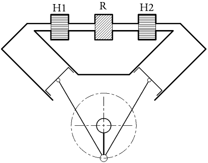
exchangers H1 and H2 and the regenerator R. In this type of
engine there are two loaded pistons operating 90 deg out
of phase. The enclosed working gasses are shifted
between the two cylinders passing through the heat
exchangers H1 and H2 and the regenerator R. |
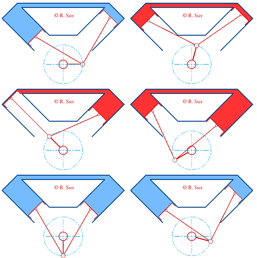
 The animation (shown right) shows how the enclosed gasses are compressed (shown blue) or expanded (shown red) The Rider engine works on a reversible cycle. If the machine is driven by, say, an electric motor then it will acts as a heat pump or refrigerator. The gasses when shifted from left to right cylinder will be expanded and the temperature falls. The gasses when moved from right to left cylinder will be compressed and the temperature rises. Heat will therefor be absorbed in the right cylinder and given up in the left cylinder. The temperature in H2 falls and rises in H1. For the machine to act as a motor, heat must be applied to the right cylinder, via H2, and abstracted, by means of a cooler, H1, from the left cylinder. The enclosed gasses will be heated and thus expanded (internal pressure rises) when moved from left to right cylinder, through the heater, H2. When the gasses are moved from right cylinder to the left, they are compressed but the heat of compression is removed by the cooler, H1, so the internal pressure falls. |
Solar Chimney Power Plants
| Solar Chimneys work on the simple principle that
hot air rises. This is the power that drove the domestic
Smoke Jack which turned, for over 300 years, the
roasting spits of Western Europe. However the Solar
Chimney utilises solar power unlike the Smoke Jack which
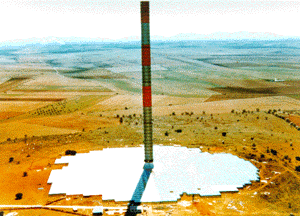
turns in the rising hot gasses of the cooking range. A tall chimney is built in the center of a large transparent solar collector. The suns rays will heat the air beneath the collector and the warmed, becoming less dense, ascends the chimney. The rising hot air will cool become denser and draw up more air in the same fashion as a tall chimney. As with normal chimneys or flues the taller the chimney the greater the draught obtained . A turbine set at the base of the chimney drives an electrical generator. Greatest power will be obtained during the day however the stored heat in the ground below the solar collector will enable the turbine to operate at reduced power during the hours of darkness. |

The first Solar Chimney Power Plant was built and
commissioned in 1983, in Manzanares, Spain. The
project was funded by a research grant awarded by the
German Federal Ministry for Research and Technology .
|

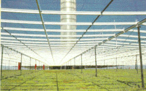
An interesting secondary use is one of Greenhouse Cultivation, since plants may be grown under 75% of of the solar collector area. The greenhouse effect provides stabile even temperature conditions. However since Solar chimneys are best sited in dry and infertile lands, in order to support intensive agriculture, additional water would be required. |
<http://sbp.de/de/html/contact/download/The_Solar_Updraft.pdf>
For information on developments in Australia see www.enviromission.com.au
<http://www.stirlingengines.org.uk/thermo/thermoc.html>
Thermoacoustic Stirling Engine
A recent
invention is the The thermoacoustic Stirling heat engine
developed by LANL
scientists. It works by creating intense acoustic energy
which can be used directly in acoustically powered
refrigerators or to generate electricity. The power production
process is environmentally friendly and up to 30 percent
efficient while typical internal combustion engines are 25 to
40 percent efficient.
A, seven chapter, 265 page book on the subject of
thermocoustics can be down loaded, in PDF format, from http://www.lanl.gov/projects/thermoacoustics/Book/index.html
Information will also be found on
----
Ben & Jerry's Uses Sound to Chill Ice Cream
Scientists have found a new way to refrigerate ice cream, by using sound waves instead of chemicals. The system, which can power a small ice-cream freezer case, is sponsored by Ben & Jerry's Ice Cream, a company known for its efforts to protect the environment.
At the heart of the system is sound — a 190-decibel note that fluctuates some 100 times per second. That expansion and compression creates pockets of cold and warm air. A system of air circulators then funnels the cool air into the ice cream case.
The new "green" freezer isn't likely to be seen in stores any time soon, because of its cost — considerably more than conventional freezers that use chemicals. But its creators say their system works, and it uses cheap components to do work currently done by exotic — and often dangerous — chemicals.
While the commercial future of the
system is uncertain, it passed a recent test at a Ben &
Jerry's store in New York. NPR's Robert Smith reports.
-------------------------------------------
<http://www.stirlingengines.org.uk/index.html>
-------------------------------------------